
Fan Laws Explained: Airflow, Pressure, Power and RPM Calculations | AS Engineers

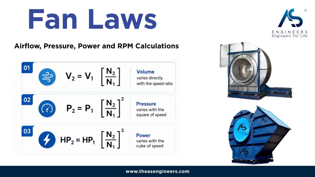
Fan laws, also called fan affinity laws, explain how the performance of the same fan changes when its rotational speed changes. When the impeller diameter and gas density remain constant, airflow changes directly with RPM, pressure changes with the square of RPM, and absorbed fan power changes with the cube of RPM.
This means that a relatively small increase in fan speed can create a much larger increase in pressure and power demand. Fan laws are therefore useful for preliminary fan calculations, VFD speed adjustments, pulley changes, retrofit studies and troubleshooting. However, the final operating condition must always be checked against the fan curve, system curve, motor capacity and mechanical speed limits.
Fan Laws at a Glance
- Airflow: Changes directly with fan RPM.
- Pressure: Changes with the square of fan RPM.
- Absorbed power: Changes with the cube of fan RPM.
What Are Fan Laws?
Fan laws are mathematical relationships used to estimate how airflow, pressure and power will change when fan speed, impeller diameter or gas density changes.
This guide focuses on the three speed-based fan laws shown in the AS Engineers fan-law chart. These laws apply when:
- The same fan and impeller are being evaluated.
- The impeller diameter remains unchanged.
- The gas density remains approximately constant.
- The fan operates under dynamically similar conditions.
- The connected duct and process system has not materially changed.
- Fan efficiency does not change significantly between the two operating points.
These calculations are commonly used for centrifugal blowers, ID fans, FD fans, exhaust fans, process fans and industrial ventilation systems. Buyers who need a broader equipment overview can first review our complete guide to centrifugal fans.
Symbols Used in Fan-Law Calculations
| Symbol | Meaning | Common Units |
|---|---|---|
| Q or V | Volume airflow rate | m³/hr, CMH, CFM or m³/s |
| ΔP | Fan pressure rise | Pa, mmWC, mmWG or mbar |
| N | Fan rotational speed | RPM |
| BHP or P | Absorbed fan shaft power | HP or kW |
| 1 | Existing or known operating condition | Existing data |
| 2 | New or required operating condition | Calculated data |
The same unit must be used for the existing and new values. Static pressure must be compared with static pressure, while total pressure must be compared with total pressure.
The Three Basic Fan Laws
| Fan Law | Formula | Relationship |
|---|---|---|
| Airflow law | Q2 = Q1 × (N2 ÷ N1) | Airflow changes directly with RPM. |
| Pressure law | ΔP2 = ΔP1 × (N2 ÷ N1)2 | Pressure changes with the square of RPM. |
| Power law | P2 = P1 × (N2 ÷ N1)3 | Absorbed power changes with the cube of RPM. |
The common value in all three formulas is the speed ratio:
Speed ratio = New RPM ÷ Existing RPM
First Fan Law: Airflow Changes Directly with RPM
The first fan law states:
Q2 = Q1 × (N2 ÷ N1)
When the rotational speed of the same fan changes, its theoretical volume airflow changes in direct proportion to the speed ratio.
- A 10% increase in RPM theoretically increases airflow by 10%.
- A 20% increase in RPM theoretically increases airflow by 20%.
- A 10% reduction in RPM theoretically reduces airflow by 10%.
Airflow Calculation Example
Suppose an industrial fan delivers 10,000 m³/hr at 1,000 RPM. The fan speed is increased to 1,200 RPM.
Speed ratio = 1,200 ÷ 1,000 = 1.2
Q2 = 10,000 × 1.2
Calculated airflow = 12,000 m³/hr
The calculation predicts a 20% increase in airflow. Actual airflow will depend on the new intersection between the fan curve and the system curve.
To understand how the impeller and housing create airflow and pressure, read our explanation of the centrifugal blower working principle.
Second Fan Law: Pressure Changes with the Square of RPM
The second fan law states:
ΔP2 = ΔP1 × (N2 ÷ N1)2
Fan pressure does not increase in direct proportion to speed. It changes with the square of the speed ratio.
Using the previous example:
- Existing speed: 1,000 RPM
- New speed: 1,200 RPM
- Existing static pressure: 500 mmWC
- Speed ratio: 1.2
ΔP2 = 500 × 1.22
ΔP2 = 500 × 1.44
Calculated static pressure = 720 mmWC
A 20% increase in fan speed produces a theoretical 44% increase in pressure.
This relationship matters in industrial systems because the fan must overcome resistance created by ducts, bends, dampers, filters, cyclones, scrubbers, bag filters, heat exchangers, silencers and process equipment.
The required pressure should be determined from the complete system resistance. It should not be assumed only from motor HP, inlet diameter or outlet size. Our centrifugal blower design guide explains the additional operating inputs that influence fan design.
Third Fan Law: Power Changes with the Cube of RPM
The third fan law states:
P2 = P1 × (N2 ÷ N1)3
Absorbed fan power changes with the cube of the speed ratio. This is the most important fan law to consider before increasing fan speed because motor loading can rise much faster than airflow.
Assume the existing absorbed fan power is 20 HP.
P2 = 20 × 1.23
P2 = 20 × 1.728
Calculated absorbed power = 34.56 HP
The speed has increased by only 20%, but the theoretical absorbed power has increased by 72.8%.
Important motor warning
The power law estimates absorbed fan shaft power. It does not automatically determine the required motor nameplate rating. Motor efficiency, transmission losses, service margin, starting condition, VFD capacity, duty cycle and the complete fan performance curve must also be reviewed.
Complete Fan-Law Calculation Example
Consider a centrifugal fan operating at the following known condition:
| Parameter | Existing Condition |
|---|---|
| Fan speed | 1,000 RPM |
| Airflow | 10,000 m³/hr |
| Static pressure | 500 mmWC |
| Absorbed power | 20 HP |
The proposed fan speed is 1,200 RPM.
Step 1: Calculate the Speed Ratio
Speed ratio = 1,200 ÷ 1,000 = 1.2
Step 2: Calculate the New Airflow
Q2 = 10,000 × 1.2 = 12,000 m³/hr
Step 3: Calculate the New Pressure
ΔP2 = 500 × 1.22 = 720 mmWC
Step 4: Calculate the New Absorbed Power
P2 = 20 × 1.23 = 34.56 HP
Calculated Performance Comparison
| Parameter | Existing | Calculated | Change |
|---|---|---|---|
| RPM | 1,000 | 1,200 | +20% |
| Airflow | 10,000 m³/hr | 12,000 m³/hr | +20% |
| Static pressure | 500 mmWC | 720 mmWC | +44% |
| Absorbed power | 20 HP | 34.56 HP | +72.8% |
The calculation does not confirm that the existing fan, shaft, impeller, bearings, drive or motor can safely operate at 1,200 RPM. The revised duty must be checked using the manufacturer’s fan curve and mechanical design limits.
Fan Speed Ratio Reference Table
| Fan Speed | Theoretical Airflow | Theoretical Pressure | Theoretical Absorbed Power |
|---|---|---|---|
| 80% | 80% | 64% | 51.2% |
| 90% | 90% | 81% | 72.9% |
| 100% | 100% | 100% | 100% |
| 110% | 110% | 121% | 133.1% |
| 120% | 120% | 144% | 172.8% |
The table demonstrates why increasing fan speed without checking the motor can result in overload. It also explains why reducing fan speed may considerably reduce theoretical absorbed power in suitable variable-flow applications.
How to Calculate the Required Fan RPM
Fan laws can also be rearranged to estimate the required RPM from a target airflow or pressure.
Required RPM from Airflow
N2 = N1 × (Q2 ÷ Q1)
Required RPM from Pressure
N2 = N1 × √(ΔP2 ÷ ΔP1)
Required RPM from Absorbed Power
N2 = N1 × ∛(P2 ÷ P1)
These formulas provide preliminary values only. The calculated RPM must be checked against the performance curve, maximum permissible impeller speed and drive arrangement.
Using Fan Laws with a VFD
A variable-frequency drive can adjust motor speed and therefore change fan RPM. Fan laws can estimate how the fan’s airflow, pressure and absorbed power may change at a different speed.
For a preliminary review, use the fan’s measured RPM rather than assuming that motor speed exactly equals its synchronous speed. Motor slip, VFD control method and mechanical transmission can create differences between calculated and actual shaft RPM.
Before changing the VFD frequency, check:
- Existing and required airflow
- Existing and required static pressure
- Current fan RPM
- Motor full-load current
- Actual operating current
- Motor and VFD ratings
- Minimum process airflow
- Fan curve and stable operating region
- Bearing and impeller speed limits
- Vibration and resonance zones
A VFD should not be used to hide system problems such as a blocked filter, closed damper, dust-filled duct or restricted fan inlet.
Using Fan Laws After a Pulley Change
In a belt-driven fan, changing the motor pulley or fan pulley changes fan RPM. The revised fan RPM can then be used in the three fan-law equations.
Before making a pulley change, verify:
- Motor speed and fan shaft speed
- Motor pulley and fan pulley diameters
- Belt speed and belt rating
- Shaft and bearing limits
- Drive guard clearance
- Belt alignment and tension
- Available motor power
- Maximum safe impeller RPM
Our guide to belt-driven industrial blowers explains where belt drives are used and what should be considered during selection.
Why Actual Fan Performance May Differ from Fan-Law Calculations
Fan laws describe theoretical relationships under controlled assumptions. Actual plant performance may differ for several reasons.
Fan Curve and System Curve Interaction
A fan curve shows the pressure a fan can develop at different airflow rates. A system curve represents the pressure required to move air or gas through the connected system.
The actual operating point occurs where the fan curve and system curve intersect. When fan speed changes, the fan curve changes, but the new duty point is still determined by its intersection with the system curve.
Changing System Resistance
System resistance can change because of:
- Dirty or blocked filters
- Dust accumulation inside ducts
- Partially closed dampers
- Added bends or duct extensions
- Modified scrubbers or bag filters
- Changes to process equipment
- Damaged flexible connections
- Changes to chimney or stack configuration
If the system has changed, old fan data may no longer represent the current duty.
Temperature and Gas Density
Gas density changes with temperature, altitude, pressure, humidity and gas composition. Hot process gas is generally less dense than cooler ambient air.
At constant speed and diameter, theoretical volume airflow remains approximately similar, while pressure and absorbed power change in proportion to gas density. A fan handling hot flue gas should therefore not be evaluated using ambient-air density without correction.
Fan Efficiency Changes
The simplified fan laws assume that efficiency remains reasonably similar. In practice, efficiency may change as the operating point moves across the fan curve.
System Effect
Sharp elbows, blocked inlets, abrupt duct transitions, uneven inlet flow and insufficient straight duct length can create turbulence or swirl near the fan. These system effects can reduce delivered performance even when the fan itself is correctly designed.
Impeller Wear or Material Build-Up
Dust build-up, corrosion, abrasion, damaged blades and an unbalanced impeller can change airflow, pressure, absorbed power and vibration. Calculations based on clean-fan data may not match a worn or contaminated fan.
Mechanical Speed Limits
Higher RPM increases impeller tip speed, centrifugal stress, bearing speed, vibration risk and noise. The maximum safe RPM must be confirmed from the fan’s mechanical design and manufacturer data.
The selected drive arrangement also affects maintenance access, alignment and mechanical reliability. Review the available centrifugal blower arrangements before finalising a drive configuration.
When Fan Laws Are Useful
Fan laws are particularly useful for preliminary evaluation of:
- VFD speed adjustments
- Pulley and belt-drive changes
- Airflow capacity increases
- Draft-control adjustments
- Fan retrofit studies
- Estimated motor-loading changes
- Production-capacity changes
- Low-airflow troubleshooting
- Energy-reduction studies
- Comparing two fan-speed conditions
They are most useful when the existing airflow, pressure, RPM and absorbed power have been measured reliably.
When Fan Laws Should Not Be Used Alone
Do not rely only on fan-law calculations when:
- The impeller diameter or blade geometry is changing.
- A different fan model or fan type is being considered.
- Gas temperature or density has changed significantly.
- The duct or process system has been modified.
- The fan is operating near stall or an unstable curve region.
- The impeller is worn, damaged, corroded or covered with deposits.
- The application contains heavy dust, corrosive gas or high temperature.
- The proposed speed may exceed mechanical limits.
- A live plant requires an exact performance guarantee.
When selecting a new fan, use the complete duty condition rather than calculating from motor HP alone. The centrifugal blower selection guide for industrial buyers covers the inputs required for proper selection.
Common Fan-Law Calculation Mistakes
Assuming Power Changes Directly with RPM
Power changes approximately with the cube of RPM, not directly with RPM. This mistake can result in serious motor under-sizing.
Using Motor Nameplate HP as Actual Fan Power
The installed motor may have additional capacity above the actual absorbed fan power. Use measured or curve-based absorbed power whenever possible.
Ignoring Gas Density
Ambient-air data should not be applied directly to hot, humid or process gas without checking density.
Ignoring the System Curve
The fan does not independently determine the final airflow. Actual performance depends on the connected system resistance.
Mixing Units
Do not mix CFM with m³/hr, or Pa with mmWC, without correct conversion. Both existing and calculated values must use consistent units.
Ignoring Maximum Safe RPM
Aerodynamic calculations do not prove that the impeller, shaft, drive and bearings can safely operate at the new speed.
Treating Theoretical Results as Guaranteed Performance
Fan laws provide estimates. Final performance should be confirmed through fan curves, manufacturer review and field measurements.
Practical Checks Before Increasing Fan Speed
When I review a proposed fan speed increase, I do not begin by changing the VFD frequency or pulley diameter. I first establish the existing operating duty and determine whether the performance problem comes from the fan, the system or both.
- Record the existing fan RPM.
- Measure or confirm the existing airflow.
- Measure inlet and outlet pressure.
- Record motor current and actual absorbed power where available.
- Confirm gas temperature, density and composition.
- Inspect ducts, dampers, filters, scrubbers and cyclones.
- Check the impeller for dust build-up, erosion or corrosion.
- Calculate the proposed performance using fan laws.
- Obtain or calculate the revised fan curve.
- Compare the fan curve with the system curve.
- Confirm motor, VFD, coupling or belt-drive capacity.
- Confirm the maximum safe fan RPM.
- Check vibration, noise and bearing temperature after adjustment.
- Measure and record the new operating point.
For existing equipment, AS Engineers also provides centrifugal blower performance analysis, repair, balancing, alignment and retrofit support.
Information Required for a Fan Speed or Retrofit Review
| Required Input | Information to Provide |
|---|---|
| Application | Boiler, furnace, dryer, bag filter, scrubber, dust collector, kiln or process exhaust |
| Existing airflow | CFM, CMH, m³/hr or m³/s |
| Required airflow | Target flow at actual operating conditions |
| Pressure | Existing and required static or total pressure |
| Fan speed | Existing measured RPM and proposed RPM |
| Gas condition | Temperature, density, humidity, composition and altitude |
| Dust load | Dust type, concentration, particle size, stickiness and abrasiveness |
| Impeller | Diameter, blade type, MOC and present condition |
| Motor | HP or kW, full-load current, actual current and service factor |
| Drive arrangement | Direct drive, belt drive or coupling drive |
| Connected system | Ducts, bends, dampers, filters, pollution-control equipment and stack |
| Existing problem | Low airflow, low suction, high current, vibration, noise or overheating |
Technical Reference for Fan Laws
The relationships explained in this article align with AMCA’s Fundamentals of Airflow. AMCA also explains that poor inlet and outlet conditions can create system-effect losses that reduce installed fan performance.
These references support preliminary engineering calculations. Final fan speed, motor power and mechanical suitability should still be confirmed for the actual application.
Frequently Asked Questions
What are the three basic fan laws?
The three basic fan laws state that airflow changes directly with fan RPM, pressure changes with the square of RPM, and absorbed power changes with the cube of RPM. These relationships apply when the same fan, impeller diameter and gas density are maintained under dynamically similar conditions.
What happens when fan speed increases by 10%?
A 10% increase in fan speed theoretically produces 10% more airflow, 21% more pressure and approximately 33.1% more absorbed power. Motor capacity and maximum safe fan RPM must be checked before making the change.
Does reducing fan speed reduce power consumption?
Under ideal fan-law conditions, reducing fan speed reduces absorbed fan power approximately with the cube of the speed ratio. Actual electrical consumption also depends on fan efficiency, motor efficiency, VFD efficiency and the real system operating point.
Can fan laws determine the correct motor size?
Fan laws can estimate the change in absorbed fan power, but they do not independently determine the correct motor size. Motor efficiency, transmission losses, service margin, starting condition, duty cycle and the full fan performance curve must also be considered.
Do fan laws apply when the impeller diameter changes?
The three formulas explained in this article apply to speed changes at constant impeller diameter and gas density. Different affinity relationships apply to geometrically similar fans when impeller diameter changes. Impeller trimming or replacement should be evaluated using manufacturer performance data because efficiency and geometry may not remain similar.
Conclusion
Fan laws provide a practical method for estimating how a change in RPM affects the same fan. Airflow changes directly with speed, pressure changes with speed squared, and absorbed fan power changes with speed cubed.
The power law is especially important because a small RPM increase can create a much larger motor-load increase. A proposed speed change must therefore be checked against the fan curve, system curve, gas density, motor rating, VFD or drive capacity, impeller design, bearing limits and maximum safe RPM.
If you are reviewing an industrial centrifugal blower, share the airflow, static pressure, gas temperature, density, dust load, current RPM, motor details, duct arrangement and actual operating problem.
AS Engineers can review the duty condition before suggesting a fan selection, speed adjustment, performance study, repair or retrofit approach.
Discuss Your Industrial Fan Requirement
Share your airflow, pressure, temperature, gas condition, dust load and operating duty with the AS Engineers team.
Phone: +91 990 903 3851
Phone: +91 823 867 7554
Email: info@theasengineers.com
Enquiry: Contact AS Engineers
